
These instructions describe how to replace the track rod ends.
NOTE: ANY WORK THAT YOU PERFORM ON YOUR OWN OR SOMEONE ELSE'S CAR IS ENTIRELY YOUR OWN RESPONSIBILITY. PLEASE DO NOT ATTEMPT THIS WORK IF YOU ARE NOT CONFIDENT YOU CAN COMPLETE IT SAFELY. ALWAYS FOLLOW GOOD WORKING PRACTICES AND NEVER TAKE RISKS OR SHORT CUTS. WHILST EVERY EFFORT HAS BEEN MADE TO ENSURE THAT THESE INSTRUCTIONS ARE COMPLETE THEY SHOULD ONLY BE CONSIDERED A GUIDE - NO GUARANTEE IS MADE THAT THEY ARE COMPLETE OR EXHAUSTIVE.
PLEASE READ THESE INSTRUCTIONS THROUGH COMPLETELY AND THOROUGHLY BEFORE STARTING THE WORK. IF YOU ARE IN ANY DOUBT OR HAVE ANY QUESTIONS PLEASE CONTACT US AT instructions@tadts.com.
If you have any comments/suggestions or notice any errors/omissions please let us know at instructions@tadts.com.
General working recommendations
When removing parts from a car it is always a good idea to place them in a container rather than leaving
them on the floor. This reduces the risk of damaging them by treading on them and also keeps them cleaner
and easier to move around. Something like an old metal tray or biscuit tin is ideal - large enough to hold
most parts, strong enough to take the weight and robust enough to last.
Be methodical about the work and wherever possible work on a small part of the car at a time. This will help you be able to remember what you have done so that reassembly is easier.
Try and be tidy as you work - put tools back on a bench/in a box as they can be dangerous left lying around on the floor and are more difficult to find.
Please read these instructions through thoroughly before starting the work. If you have any questions/comments please feel free to contact us at the email address given at the top of the page.
Estimated time required: 1 hour 10 minutes
Please note that this estimated time is a rough guide and is based on a relatively inexperienced person
performing the task for the first time. It should cover most 'worst-case' scenarios and you will
probably find you complete the task in much less time.
Tools required
| - Suitable jack and protective pad (e.g. a piece of wood) | - Two chocks (e.g. house bricks) |
| - Axle stands/substantial pieces of wood/full boxes of paper | - Wire brush |
| - Large mole grips | - Ball joint splitter |
| - Steel rule | - Wire cutters |
| - Small mole grips | - Four ramps |
| - 19mm socket | - Socket handle and extension bars |
| - Road wheel bolt special tool (S2 only - supplied with car) | - 17mm socket |
| - Road wheel locking nut/bolt key (supplied with car) | - Breaker bar |
| - Torque wrench | - 19mm open-ended spanner x2 |
| - 17mm ring spanner |
Materials required
| - WD40 or similar | - New track rod end(s) |
| - Rag/cloth/tissue | - Cable ties |
| - Copper grease |
Torque settings
| - Track rod end to steering arm nut 30 Nm | |
| - Track rod end locknuts 80-82Nm | - S1 road wheel nut 85 Nm |
| - S2 road wheel bolt 105 Nm |
To allow better acces to the steering/suspension/brakes turn the steering onto full lock. If you are working on the left-hand side then turn the steering wheel fully clockwise. If you are working on the right-hand side turn the wheel fully anti-clockwise.
![]() Before raising a car with the front wheels turned always ensure it is firmly chocked and that the handbrake is firmly applied. Also do not raise the car too high with the front wheels turned. If required raise the car completely, remove the engine undertray and diffuser panel, support the car on axle stands or similar and then remove the road wheels. This will give you complete access and ability to move the steering as much as you want.
Before raising a car with the front wheels turned always ensure it is firmly chocked and that the handbrake is firmly applied. Also do not raise the car too high with the front wheels turned. If required raise the car completely, remove the engine undertray and diffuser panel, support the car on axle stands or similar and then remove the road wheels. This will give you complete access and ability to move the steering as much as you want.
Tools required
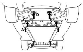
The Elise has a single jacking point each side that raises both wheels on one side at the same time. This should be
marked with a blue and white sticker with a picture of a trolley jack on it (point A in the diagram).
If the car you are working on does not have this sticker the correct jacking point is on the main
chassis rail at the point where the cockpit floor and engine undertray meet.
When raising the car use a piece of wood or similar to protect the chassis from direct contact with the saddle
of the jack.
Before raising the car, firmly apply the handbrake and chock the wheels on the opposite side to the one
you are going to raise. Carefully line up the jack up at the correct point and start to lift. Continue to raise
the car until it is at the required height.
Place some supports such as axle stands, full boxes of paper of substantial pieces of wood under the support points
(points B and D in the diagram) before continuing the work.
![]() Never work under or near a car that is only supported on a jack. Always use some additional means of
support such as axle stands. Even a full box of paper under the chassis rail is sufficient.
Never work under or near a car that is only supported on a jack. Always use some additional means of
support such as axle stands. Even a full box of paper under the chassis rail is sufficient.
- Suitable jack and protective pad (e.g. a piece of wood)
- Two chocks (e.g. house bricks)
- Axle stands/substantial pieces of wood/full boxes of paper
![]() Since there is no way of securely locating the jack on an Elise be careful about raising one side too much
higher than the other as there is a chance that the jack will slip out causing injury and damage the sill.
Since there is no way of securely locating the jack on an Elise be careful about raising one side too much
higher than the other as there is a chance that the jack will slip out causing injury and damage the sill.
![]() When placing the jack and protective pad ensure that you place it directly onto the flat surface of the
chassis rail and not onto any the fixings that are in that area.
When placing the jack and protective pad ensure that you place it directly onto the flat surface of the
chassis rail and not onto any the fixings that are in that area.
Tools required
The S1 has 19mm hex head nuts and the S2 has 17mm hex head bolts (with the special tool).
Before undoing the road wheel nuts/bolts raise the car slightly so that some of the weight is taken on the jack. Do not raise it too far
otherwise the wheels will turn as you attempt to undo the road wheel nuts/bolts.
Place the support(s) under the correct locations and then remove the road wheel nuts/bolts (placing all the nuts/bolts/security nuts/covers in a
suitable container) and then remove the wheel from the car.
Place the removed road wheel somewhere they will not get damaged and out of the way. Also ensure that they are secure and won't fall over - i.e. don't leave them 'upright' on the tyre tread.
- 19mm socket
- Socket handle and extension bars
- Road wheel bolt special tool (S2 only - supplied with car)
- 17mm socket
- Road wheel locking nut/bolt key (supplied with car)
- Breaker bar
![]() S1 only - covering the outside of the socket you use to undo the road wheel nuts with
electrical insulation tape or similar will help prevent damage to the wheels.
S1 only - covering the outside of the socket you use to undo the road wheel nuts with
electrical insulation tape or similar will help prevent damage to the wheels.
![]() S2 only - the S2 has a special tool for the road wheel bolts. This should be included with
the tool kit car for the car.
S2 only - the S2 has a special tool for the road wheel bolts. This should be included with
the tool kit car for the car.
![]() S1 only - the locking wheel nuts have covers on them. These covers have a 'slot' across them
to distinguish them from the normal nuts. To remove the cover place the black plastic tube that the locking wheel nut key is stored in over
the cover and press firmly until it clicks on. Then remove the plastic tube and the cover should come off the nut.
S1 only - the locking wheel nuts have covers on them. These covers have a 'slot' across them
to distinguish them from the normal nuts. To remove the cover place the black plastic tube that the locking wheel nut key is stored in over
the cover and press firmly until it clicks on. Then remove the plastic tube and the cover should come off the nut.
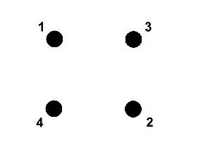 Loosen all four nuts/bolts just one turn in the sequence shown. Then continue to
raise the car until the tyre is clear of the ground and the car is at the desired height.
Loosen all four nuts/bolts just one turn in the sequence shown. Then continue to
raise the car until the tyre is clear of the ground and the car is at the desired height.
![]() Make sure when you loosen the road wheel locking nut/bolt the key that is firmly and squarely applied to the nut/bolt. These keys have a tendancy to 'round' if they are not properly used.
Make sure when you loosen the road wheel locking nut/bolt the key that is firmly and squarely applied to the nut/bolt. These keys have a tendancy to 'round' if they are not properly used.
![]() The wheel on S2s have a tendancy to fall off the hub/drive flange since they are not located on studs. To prevent this simply place your foot or knee gently against the bottom of the tyre before removing the road wheel bolts. Once the bolts are removed you can carefully remove the road wheel.
The wheel on S2s have a tendancy to fall off the hub/drive flange since they are not located on studs. To prevent this simply place your foot or knee gently against the bottom of the tyre before removing the road wheel bolts. Once the bolts are removed you can carefully remove the road wheel.
![]() You may find that the wheel and disc have corroded
together. This is especially common on cars with steel brake discs (as opposed to the earlier cars with MMC
brake discs). If this is the case a sharp bang on the tyre at 12 o'clock should free the wheel. Make sure if you do this that you've placed
your foot or knee against the bottom of the tyre to prevent the wheel falling off.
You may find that the wheel and disc have corroded
together. This is especially common on cars with steel brake discs (as opposed to the earlier cars with MMC
brake discs). If this is the case a sharp bang on the tyre at 12 o'clock should free the wheel. Make sure if you do this that you've placed
your foot or knee against the bottom of the tyre to prevent the wheel falling off.
Tools required
Materials required
Apply some WD40 or similar to the visible part of the track rod end shaft and to the visible part of the track rod thread.
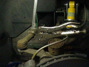
Slacken the locknut(s) on the track rod as shown in the photograph using a 19mm hex head open-ended spanner
taking care to ensure the spanner is properly on the nut as these tend to be very tight.
Once both locknuts have been loosened turn them back up to the track rod end body but only finger-tight.
Now hold the locknut(s) on the track rod and unwind the track rod end from the track rod end.
- Wire brush
- Large mole grips
- Ball joint splitter
- 19mm open-ended spanner x2
- Socket handle and extension bars
- 17mm socket
- WD40 or similar
 Thoroughly clean the visible part of the track rod end shaft thread and also the visible part of the track rod thread with a wire brush.
![]() It is preferable to use a spanner on the track rod end body rather than mole grips if possible.
Some track rod ends are manufactured to allow a 19mm spanner to securely hold them.
It is preferable to use a spanner on the track rod end body rather than mole grips if possible.
Some track rod ends are manufactured to allow a 19mm spanner to securely hold them.
![]() Some cars have one locknut on each side and some have two. Make sure that if the car you are working on has
two you loosen the inboard one first.
Some cars have one locknut on each side and some have two. Make sure that if the car you are working on has
two you loosen the inboard one first.
![]() When loosening the track rod end locknut(s) make sure the spanner is correctly seated on the nut. These locknuts are typically very tight and it is easy to damage the edges/corners of the nut.
When loosening the track rod end locknut(s) make sure the spanner is correctly seated on the nut. These locknuts are typically very tight and it is easy to damage the edges/corners of the nut.
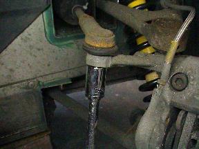 Use a 19mm hex head socket to remove the nut on the track rod end shaft. Once the nut is removed use
a ball joint splitter to separate the track rod end from the steering arm.
Use a 19mm hex head socket to remove the nut on the track rod end shaft. Once the nut is removed use
a ball joint splitter to separate the track rod end from the steering arm.
Tools required
Materials required
Torque settings
Ensure that the machined cone in the steering arm is completely smooth and free from debris.
Place the track rod end into the steering arm and carefully tighten the nut so
that the shaft is not disturbed. It is best to do this with a ring spanner to avoid disturbing the shaft.
Tighten the nut to 30 Nm using a 19mm hex head
socket.
Now you need to insert the track rod into the track rod end. The easiest way to do this is to manipulate the track rod end track rod so that
they are in line with each other and touching (you may have to turn the hub carrier/upright to achieve this).
Once they are touching apply gentle pressure to the steering arm to push the track rod end against the track rod. Turn the track rod (which may require
a pair of grips or similar) until the locknut(s) are just touching the track rod end body.
Tighten the locknut(s) to 80-82Nm.
- 17mm socket
- Socket handle and extension bars
- Torque wrench
- 19mm open-ended spanner x2
- 17mm ring spanner
- Steel rule
- Wire cutters
- Small mole grips
- New track rod end(s)
- Rag/cloth/tissue
- Cable ties
- Track rod end to steering arm nut 30 Nm
- Track rod end locknuts 80-82Nm
![]() When tightening the nut onto the new track rod end shaft take great care not to
disturb the shaft. The reason for this is that if the shaft is disturbed it may rotate as you turn the nut.
When tightening the nut onto the new track rod end shaft take great care not to
disturb the shaft. The reason for this is that if the shaft is disturbed it may rotate as you turn the nut.
![]() If the track rod end shaft does start to turn as you are tightening the nut use a
pair of mole grips or similar to firmly hold the track rod end onto the steering arm. This
should provide enough friction to prevent the shaft from turning.
If the track rod end shaft does start to turn as you are tightening the nut use a
pair of mole grips or similar to firmly hold the track rod end onto the steering arm. This
should provide enough friction to prevent the shaft from turning.
![]() To get the front toe/tracking as close as possible to how it was measure the distance between the
'centre' of the ball joint of the track rod end and the end of the body of the old item. Also measure the same dimension of the new item.
Move the locknut(s) along the track rod by the difference between these two measurements.
To get the front toe/tracking as close as possible to how it was measure the distance between the
'centre' of the ball joint of the track rod end and the end of the body of the old item. Also measure the same dimension of the new item.
Move the locknut(s) along the track rod by the difference between these two measurements.
![]() You may find that you need to cut the cable tie on the steering rack gaiter to allow the track rod to turn easily. To do this use a pair of wire cutters carefully.
You may find that you need to cut the cable tie on the steering rack gaiter to allow the track rod to turn easily. To do this use a pair of wire cutters carefully.
![]() Since it is not possible to get a normal torque wrench and socket onto the track rod end locknut(s) using a pair
of good quality 19mm hex head open-ended spanners and doing them up very tightly is sufficient.
Since it is not possible to get a normal torque wrench and socket onto the track rod end locknut(s) using a pair
of good quality 19mm hex head open-ended spanners and doing them up very tightly is sufficient.
![]() When tightening the track rod end locknut(s) take care not to turn the track rod end so that the
torque is being applied to the track rod end ball joint. Always hold the track rod body either with an open-ended spanner or some grips.
When tightening the track rod end locknut(s) take care not to turn the track rod end so that the
torque is being applied to the track rod end ball joint. Always hold the track rod body either with an open-ended spanner or some grips.
Tools required
Materials required
The S1 has 19mm hex head nuts and the S2 has 17mm hex head bolts (with the special tool).
Put a thin smear of copper grease or similar on the outer face of the brake disc where it comes into contact with the road wheel. This will
help prevent the two corroding together. Also put a thin smear of copper grease on the road wheel studs/wheel bolts.
Carefully lift the road wheel into position. On an S1 this will mean placing the road wheel over the studs on the hub/drive flange. On an S2 you need
to make sure that the bolt holes in the wheel line up with the bolt holes in the disc.
Hold the wheel in place by placing your foot or knee gently against the bottom of the tyre and put the nuts/bolts back. At this stage just finger-tight is
sufficient.
Once all four nuts/bolts are in place and finger-tight use a socket handle to just nip them up a little bit more. Don't overtighten them but make sure the wheel isn't loose.
- 19mm socket
- 17mm socket
- Socket handle and extension bars
- Road wheel bolt special tool (S2 only - supplied with car)
- Road wheel locking nut/bolt key (supplied with car)
- Copper grease
- Rag/cloth/tissue
![]() It is worth putting a little copper grease or similar on the road wheel studs/bolts as it will help with
subsequent removal.
It is worth putting a little copper grease or similar on the road wheel studs/bolts as it will help with
subsequent removal.
![]() S1 only - covering the outside of the socket you use to tighten the road wheel nuts with
electrical insulation tape or similar will help prevent damage to the wheels.
S1 only - covering the outside of the socket you use to tighten the road wheel nuts with
electrical insulation tape or similar will help prevent damage to the wheels.
![]() S2 only - the S2 has a special tool for the road wheel bolts. This should be included with
the tool kit car for the car.
S2 only - the S2 has a special tool for the road wheel bolts. This should be included with
the tool kit car for the car.
Tools required
Lowering the car is the reverse of raising it - locate the jack/protective pad at the correct point and
raise the car clear of the support(s). Remove the support(s) and carefully lower the car until it is resting on
the floor.
- Suitable jack and protective pad (e.g. a piece of wood)
- Four ramps
Tools required
Torque settings
With the tyres in contact with something firm (the ground, a ramp etc.) use a torque wrench to tighten up the road wheel nuts/bolts
in the same sequence as they were loosened. The S1 setting is 85 Nm and the S2 setting is
105 Nm.
- 19mm socket
- 17mm socket
- Socket handle and extension bars
- Torque wrench
- Road wheel bolt special tool (S2 only - supplied with car)
- Road wheel locking nut/bolt key (supplied with car)
- S1 road wheel nut 85 Nm
- S2 road wheel bolt 105 Nm
![]() Make sure when you use the road wheel locking nut/bolt key that is firmly and squarely applied
to the nut/bolt. These keys have a tendancy to 'round' if they are not properly used.
Make sure when you use the road wheel locking nut/bolt key that is firmly and squarely applied
to the nut/bolt. These keys have a tendancy to 'round' if they are not properly used.
![]() S1 only - to fit the covers to the locking wheel nuts place the cover in the end of the black
plastic tube that the locking wheel nut key is stored in and then use the plastic tube to hold the cover against the locking wheel nut.
Use a long thin flat-ended tool (a socket extension bar is suitable) to press the cover over the locking wheel nut.
S1 only - to fit the covers to the locking wheel nuts place the cover in the end of the black
plastic tube that the locking wheel nut key is stored in and then use the plastic tube to hold the cover against the locking wheel nut.
Use a long thin flat-ended tool (a socket extension bar is suitable) to press the cover over the locking wheel nut.
![]() S1 only - make sure that you only fit the locking wheel nut covers to the locking wheel nuts. If the cover does not fit easily double-check that you aren't attempting to fit a cover to a normal wheel nut.
S1 only - make sure that you only fit the locking wheel nut covers to the locking wheel nuts. If the cover does not fit easily double-check that you aren't attempting to fit a cover to a normal wheel nut.