
These instructions describe how to replace the front and rear brake pads.
Note: Take suitable precautions to protect yourself from the brake dust that is present in and around the brake pads.
NOTE: ANY WORK THAT YOU PERFORM ON YOUR OWN OR SOMEONE ELSE'S CAR IS ENTIRELY YOUR OWN RESPONSIBILITY. PLEASE DO NOT ATTEMPT THIS WORK IF YOU ARE NOT CONFIDENT YOU CAN COMPLETE IT SAFELY. ALWAYS FOLLOW GOOD WORKING PRACTICES AND NEVER TAKE RISKS OR SHORT CUTS. WHILST EVERY EFFORT HAS BEEN MADE TO ENSURE THAT THESE INSTRUCTIONS ARE COMPLETE THEY SHOULD ONLY BE CONSIDERED A GUIDE - NO GUARANTEE IS MADE THAT THEY ARE COMPLETE OR EXHAUSTIVE.
PLEASE READ THESE INSTRUCTIONS THROUGH COMPLETELY AND THOROUGHLY BEFORE STARTING THE WORK. IF YOU ARE IN ANY DOUBT OR HAVE ANY QUESTIONS PLEASE CONTACT US AT instructions@tadts.com.
If you have any comments/suggestions or notice any errors/omissions please let us know at instructions@tadts.com.
General working recommendations
When removing parts from a car it is always a good idea to place them in a container rather than leaving
them on the floor. This reduces the risk of damaging them by treading on them and also keeps them cleaner
and easier to move around. Something like an old metal tray or biscuit tin is ideal - large enough to hold
most parts, strong enough to take the weight and robust enough to last.
Be methodical about the work and wherever possible work on a small part of the car at a time. This will help you be able to remember what you have done so that reassembly is easier.
Try and be tidy as you work - put tools back on a bench/in a box as they can be dangerous left lying around on the floor and are more difficult to find.
Please read these instructions through thoroughly before starting the work. If you have any questions/comments please feel free to contact us at the email address given at the top of the page.
Estimated time required: 2 hours 35 minutes
Please note that this estimated time is a rough guide and is based on a relatively inexperienced person
performing the task for the first time. It should cover most 'worst-case' scenarios and you will
probably find you complete the task in much less time.
Tools required
| - Suitable jack and protective pad (e.g. a piece of wood) | - Two chocks (e.g. house bricks) |
| - Axle stands/substantial pieces of wood/full boxes of paper | - Pliers |
| - Small hammer | - Old toothbrush |
| - Small pin (e.g. old nail) | - Long thin lever (e.g. old tyre lever) |
| - Drill and suitable drill bits | - Small mole grips |
| - Large hammer | - Blunt flat-bladed screwdriver |
| - Four ramps | - 19mm socket |
| - Socket handle and extension bars | - Road wheel bolt special tool (S2 only - supplied with car) |
| - 17mm socket | - Road wheel locking nut/bolt key (supplied with car) |
| - Breaker bar | - 4mm allen key bit |
| - Torque wrench | - Brake piston spreader |
| - Rear brake caliper pison winding tool |
Materials required
| - Newspaper | - Rag/cloth/tissue |
| - Brake cleaner or methylated spirits | - An assistant! |
| - Copper grease | - Oil (for lubricating drill) |
Torque settings
| - S1 road wheel nut 85 Nm |
| - S2 road wheel bolt 105 Nm |
Tools required
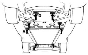
The Elise has a single jacking point each side that raises both wheels on one side at the same time. This should be
marked with a blue and white sticker with a picture of a trolley jack on it (point A in the diagram).
If the car you are working on does not have this sticker the correct jacking point is on the main
chassis rail at the point where the cockpit floor and engine undertray meet.
When raising the car use a piece of wood or similar to protect the chassis from direct contact with the saddle
of the jack.
Before raising the car, firmly apply the handbrake and chock the wheels on the opposite side to the one
you are going to raise. Carefully line up the jack up at the correct point and start to lift. Continue to raise
the car until it is at the required height.
Place some supports such as axle stands, full boxes of paper of substantial pieces of wood under the support points
(points B and D in the diagram) before continuing the work.
![]() Never work under or near a car that is only supported on a jack. Always use some additional means of
support such as axle stands. Even a full box of paper under the chassis rail is sufficient.
Never work under or near a car that is only supported on a jack. Always use some additional means of
support such as axle stands. Even a full box of paper under the chassis rail is sufficient.
- Suitable jack and protective pad (e.g. a piece of wood)
- Two chocks (e.g. house bricks)
- Axle stands/substantial pieces of wood/full boxes of paper
![]() Since there is no way of securely locating the jack on an Elise be careful about raising one side too much
higher than the other as there is a chance that the jack will slip out causing injury and damage the sill.
Since there is no way of securely locating the jack on an Elise be careful about raising one side too much
higher than the other as there is a chance that the jack will slip out causing injury and damage the sill.
![]() When placing the jack and protective pad ensure that you place it directly onto the flat surface of the
chassis rail and not onto any the fixings that are in that area.
When placing the jack and protective pad ensure that you place it directly onto the flat surface of the
chassis rail and not onto any the fixings that are in that area.
Tools required
The S1 has 19mm hex head nuts and the S2 has 17mm hex head bolts (with the special tool).
Before undoing the road wheel nuts/bolts raise the car slightly so that some of the weight is taken on the jack. Do not raise it too far
otherwise the wheels will turn as you attempt to undo the road wheel nuts/bolts.
Place the support(s) under the correct locations and then remove the road wheel nuts/bolts (placing all the nuts/bolts/security nuts/covers in a
suitable container) and then remove the wheel from the car.
Place the removed road wheel somewhere they will not get damaged and out of the way. Also ensure that they are secure and won't fall over - i.e. don't leave them 'upright' on the tyre tread.
- 19mm socket
- Socket handle and extension bars
- Road wheel bolt special tool (S2 only - supplied with car)
- 17mm socket
- Road wheel locking nut/bolt key (supplied with car)
- Breaker bar
![]() S1 only - covering the outside of the socket you use to undo the road wheel nuts with
electrical insulation tape or similar will help prevent damage to the wheels.
S1 only - covering the outside of the socket you use to undo the road wheel nuts with
electrical insulation tape or similar will help prevent damage to the wheels.
![]() S2 only - the S2 has a special tool for the road wheel bolts. This should be included with
the tool kit car for the car.
S2 only - the S2 has a special tool for the road wheel bolts. This should be included with
the tool kit car for the car.
![]() S1 only - the locking wheel nuts have covers on them. These covers have a 'slot' across them
to distinguish them from the normal nuts. To remove the cover place the black plastic tube that the locking wheel nut key is stored in over
the cover and press firmly until it clicks on. Then remove the plastic tube and the cover should come off the nut.
S1 only - the locking wheel nuts have covers on them. These covers have a 'slot' across them
to distinguish them from the normal nuts. To remove the cover place the black plastic tube that the locking wheel nut key is stored in over
the cover and press firmly until it clicks on. Then remove the plastic tube and the cover should come off the nut.
 Loosen all four nuts/bolts just one turn in the sequence shown. Then continue to
raise the car until the tyre is clear of the ground and the car is at the desired height.
Loosen all four nuts/bolts just one turn in the sequence shown. Then continue to
raise the car until the tyre is clear of the ground and the car is at the desired height.
![]() Make sure when you loosen the road wheel locking nut/bolt the key that is firmly and squarely applied to the nut/bolt. These keys have a tendancy to 'round' if they are not properly used.
Make sure when you loosen the road wheel locking nut/bolt the key that is firmly and squarely applied to the nut/bolt. These keys have a tendancy to 'round' if they are not properly used.
![]() The wheel on S2s have a tendancy to fall off the hub/drive flange since they are not located on studs. To prevent this simply place your foot or knee gently against the bottom of the tyre before removing the road wheel bolts. Once the bolts are removed you can carefully remove the road wheel.
The wheel on S2s have a tendancy to fall off the hub/drive flange since they are not located on studs. To prevent this simply place your foot or knee gently against the bottom of the tyre before removing the road wheel bolts. Once the bolts are removed you can carefully remove the road wheel.
![]() You may find that the wheel and disc have corroded
together. This is especially common on cars with steel brake discs (as opposed to the earlier cars with MMC
brake discs). If this is the case a sharp bang on the tyre at 12 o'clock should free the wheel. Make sure if you do this that you've placed
your foot or knee against the bottom of the tyre to prevent the wheel falling off.
You may find that the wheel and disc have corroded
together. This is especially common on cars with steel brake discs (as opposed to the earlier cars with MMC
brake discs). If this is the case a sharp bang on the tyre at 12 o'clock should free the wheel. Make sure if you do this that you've placed
your foot or knee against the bottom of the tyre to prevent the wheel falling off.
To allow better acces to the steering/suspension/brakes turn the steering onto full lock. If you are working on the left-hand side then turn the steering wheel fully clockwise. If you are working on the right-hand side turn the wheel fully anti-clockwise.
![]() Before raising a car with the front wheels turned always ensure it is firmly chocked and that the handbrake is firmly applied. Also do not raise the car too high with the front wheels turned. If required raise the car completely, remove the engine undertray and diffuser panel, support the car on axle stands or similar and then remove the road wheels. This will give you complete access and ability to move the steering as much as you want.
Before raising a car with the front wheels turned always ensure it is firmly chocked and that the handbrake is firmly applied. Also do not raise the car too high with the front wheels turned. If required raise the car completely, remove the engine undertray and diffuser panel, support the car on axle stands or similar and then remove the road wheels. This will give you complete access and ability to move the steering as much as you want.
Tools required
Materials required
Use pliers to carefully remove the 'R' clips from both retaining pins making sure you do not strain or bend them.
Apply light pressure to back of the anti-rattle spring with one hand and carefully withdraw the lower retaining pin. You may need to use pliers and/or a small hammer but make sure you are careful.
Once the lower retaining pin has been removed you should be able to remove the anti-rattle spring simply by lifting the bottom edge.
Now remove the top retaining pin in the same way as the lower one.
Place a piece of newspaper on the floor close by and carefully withdraw one pad and then the other. If you are planning on refitting the same pads make sure that you know which is the outer which is the inner one.
- Pliers
- Small hammer
- Newspaper
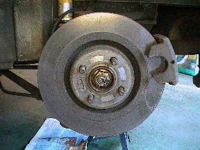
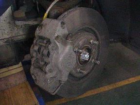 Once the front road wheel is removed you will see the brake caliper as shown in the photograph.
![]() The front brakes are practically identical between the S1 and S2 - the only differences are the shape of the anti-rattle spring and the retaining pins (which have a thinner central section on the S2).
The front brakes are practically identical between the S1 and S2 - the only differences are the shape of the anti-rattle spring and the retaining pins (which have a thinner central section on the S2).
![]() Be careful that the anti-rattle spring does not fly off as it has very sharp edges.
Be careful that the anti-rattle spring does not fly off as it has very sharp edges.
 Firmly but slowly push the caliper pistons back by squeezing the pad backplate towards the caliper body. Do this for both the inner and outer pads/pistons. This will ensure that the pads can be removed past any ridge on the edge of the disc.
![]() Always check the brake fluid level before and during this process in case there is too much
fluid in the reservoir and it overflows.
Always check the brake fluid level before and during this process in case there is too much
fluid in the reservoir and it overflows.
![]() Always put brake pads down with the friction material up and the backplate down to ensure the friction material does not get contaminated with dirt, grease etc.
Always put brake pads down with the friction material up and the backplate down to ensure the friction material does not get contaminated with dirt, grease etc.
Tools required
Materials required
Once the front brake pads have been removed you will need to thoroughly clean the caliper.
Use either brake cleaner or methylated spirits and an old toothbrush to clean the parts of the caliper that come into contact with the brake pad.
Ensure all the brake dust and other debris is removed and then wipe the whole caliper over with rag/cloth/tissue.
- Old toothbrush
- Rag/cloth/tissue
- Brake cleaner or methylated spirits
![]() If you get any contamination on the brake disc simply use methylated spirits to clean it after you have finished cleaning the caliper.
If you get any contamination on the brake disc simply use methylated spirits to clean it after you have finished cleaning the caliper.
Tools required
Materials required
Place the brake piston spreader over the brake disc and wind the tool to force both pistons fully home into the caliper
as shown in the photograph.
Remove the brake piston spreader and get an assistant to slowly and progressively depress the brake pedal while you watch
the pistons. Continue pressing the brake pedal (it will go
all the way to the floor). The pistons should move out of the caliper (one normally moves first - don't expect them to move the same
amount at the same time).
Once one or both pistons is/are protruding by a few millimetres hold the piston that is extended the most. Continue pressing the brake pedal to ensure that
the 'reluctant' piston moves freely as well.
You may find that you have to apply a lot of pressure to hold the piston. If this is the case then it is likely the other piston is slightly siezed. This
is not normally a great cause for concern - just keep an eye on that piston.
- Brake piston spreader
- An assistant!
 It is a good idea to check the operation of the front brake caliper whenever the pads are removed.
![]() Always check the brake fluid level before and during this process in case there is too much
fluid in the reservoir and it overflows.
Always check the brake fluid level before and during this process in case there is too much
fluid in the reservoir and it overflows.
![]() Make sure that you do not push the pistons too far out of the caliper as they may fall out. Always ensure that there is at least the thickness of the brake pad backplate between the piston and the disc. If in doubt always err on the side of caution - if the piston comes out brake fluid will escape and you will have to refill and bleed the brake fluid.
Make sure that you do not push the pistons too far out of the caliper as they may fall out. Always ensure that there is at least the thickness of the brake pad backplate between the piston and the disc. If in doubt always err on the side of caution - if the piston comes out brake fluid will escape and you will have to refill and bleed the brake fluid.
![]() Sometimes simply pushing the pistons fully home into the caliper and extending them with the brake pedal as above several times is enough to free a sticky piston.
Sometimes simply pushing the pistons fully home into the caliper and extending them with the brake pedal as above several times is enough to free a sticky piston.
![]() If one of both of the pistons will not move at all or is extremely stiff then it is a good idea to take the car to a professional and get their opinion.
If one of both of the pistons will not move at all or is extremely stiff then it is a good idea to take the car to a professional and get their opinion.
Tools required
Materials required
Place the brake piston spreader over the brake disc and wind the tool to force both pistons fully home into the caliper.
Put a very thin smear of copper grease on the short sides of the brake pad backplate only. You can also put some copper grease on the
back of the backplate where it comes into contact with the piston.
Insert a brake pad into the caliper ensuring that the backplate is next to the caliper and the friction material is next to the
brake disc. Put the lower retaining pin through the caliper and just into the hole in the backplate to prevent the pad from falling or moving.
Repeat for the other pad but this time put the upper retaining pin all the way through both pads and the caliper and fit it's 'R' clip.
Remove the partially-inserted lower retaining pin and place the anti-rattle spring in place. The photo shows the correct orientation for the S1 anti-rattle spring. The S2 anti-rattle spring has an arrow on it which should point upwards.
Once the anti-rattle spring is back in place apply light pressure to the back of it with one hand and carefully insert the lower retaining pin all the way through both pads and the caliper and fit it's 'R' clip.
- Brake piston spreader
- Small hammer
- Brake cleaner or methylated spirits
- Rag/cloth/tissue
- Copper grease
 If the old brake pads are to be re-used thoroughly clean them with brake cleaner or methylated spirits.
![]() Always check the brake fluid level before and during this process in case there is too much
fluid in the reservoir and it overflows.
Always check the brake fluid level before and during this process in case there is too much
fluid in the reservoir and it overflows.
![]() Some aftermarket brake pads can be a tight fit in the caliper. If the pad will not go into the
caliper easily gently and carefully tap the pad in with a small hammer. Make sure you only tap the backplate and not the friction material.
Some aftermarket brake pads can be a tight fit in the caliper. If the pad will not go into the
caliper easily gently and carefully tap the pad in with a small hammer. Make sure you only tap the backplate and not the friction material.
Tools required
Materials required
S2 only - firmly apply the handbrake and remove the 4mm cap head brake disc retaining screw.
Release the handbrake.
Tap the tool/pin/nail to push the retaining pin out of the caliper.
Once the pin has been pushed out sufficiently use a pair of pliers to pull the retaining pin out of the caliper.
Place a piece of newspaper on the floor close by ready to put the pads on.
It is not possible to simply push the rear piston back into the caliper (the piston has to be turned at the same time). The best way is to push the outer pad towards the centre of the disc so that the 'ears' on the pad are clear of the caliper. Now rotate the disc and push the disc in the same direction. This should enable you to remove the outer pad.
Remove the brake disc and then the inner pad.
Make sure that when you are using a lever it is against a strong part of the upright and pushing against the inner part of the disc. The closer you can get to the centre of the disc the better.
If the disc will still not release having tried to lever it off then you will have to tap it off with a hammer. Use a reasonable size hammer gently at first tapping as close as possible to the centre of the brake disc. As you tap rotate the disc. Continue tapping and rotating the disc (you may have to tap more firmly if the disc won't move).
Be careful that the disc does not fall off the drive flange/hub when tapping it off.
- Small pin (e.g. old nail)
- Small hammer
- Pliers
- Long thin lever (e.g. old tyre lever)
- Drill and suitable drill bits
- Small mole grips
- Large hammer
- 4mm allen key bit
- Socket handle and extension bars
- Newspaper
- Oil (for lubricating drill)
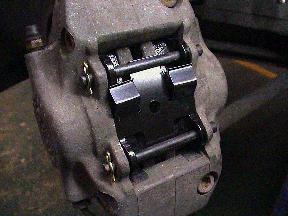
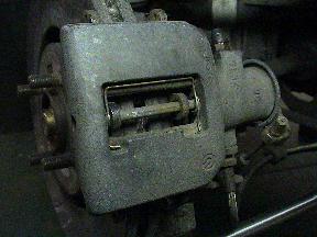
 Once the rear road wheel is removed you will see the brake caliper as shown in the photograph.
![]() The rear brakes are practically identical between the S1 and S2 - the only differences are the discs go over the road wheel studs on the S1 and the discs are retained by a 4mm cap head brake disc retaining screw on the S2.
The rear brakes are practically identical between the S1 and S2 - the only differences are the discs go over the road wheel studs on the S1 and the discs are retained by a 4mm cap head brake disc retaining screw on the S2.
![]() S2 only - it is common for the brake disc retaining screw to 'round' when you attempt to remove it. If this happens you will need to drill out the head and then remove the brake disc. Use a suitable drill and bit lubricated with a little oil and take precautions to protect both your eyes and work area from swarf.
S2 only - it is common for the brake disc retaining screw to 'round' when you attempt to remove it. If this happens you will need to drill out the head and then remove the brake disc. Use a suitable drill and bit lubricated with a little oil and take precautions to protect both your eyes and work area from swarf.
 Insert a suitable pin (an old nail or even a broken allen key is suitable) into the hole in the back of the caliper. Note that whatever tool you use should be blunt and not too thin.
![]() You may find it easier to hold the tool/pin/nail in a pair of pliers to prevent hitting your hand with the hammer.
You may find it easier to hold the tool/pin/nail in a pair of pliers to prevent hitting your hand with the hammer.
![]() If the retaining pin does not move relatively easily with tapping try using a pair of small mole grips to firmly hold the pin in line with the disc (using the hole in the back of the caliper for access). Gently tapping the mole grips should move the retaining pin.
If the retaining pin does not move relatively easily with tapping try using a pair of small mole grips to firmly hold the pin in line with the disc (using the hole in the back of the caliper for access). Gently tapping the mole grips should move the retaining pin.
![]() Take care when withdrawing the retaining pin to only hold the end of the pin itself and not the spring-metal ring on the end.
Take care when withdrawing the retaining pin to only hold the end of the pin itself and not the spring-metal ring on the end.
![]() Before fully removing the retaining pin cover the anti-rattle spring with your hand to prevent it flying off and hitting you or something else
Before fully removing the retaining pin cover the anti-rattle spring with your hand to prevent it flying off and hitting you or something else
![]() Always put brake pads down with the friction material up and the backplate down to ensure the friction material does not get contaminated with dirt, grease etc.
Always put brake pads down with the friction material up and the backplate down to ensure the friction material does not get contaminated with dirt, grease etc.
 S1 only - turn the brake disc so it matches the photograph.
![]() Always put brake discs somewhere safe where they will not get damaged or contaminated with dirt, grease etc.
Always put brake discs somewhere safe where they will not get damaged or contaminated with dirt, grease etc.
![]() Note that the brake disc may be corroded onto the drive flange. If this is the case first check you have removed the retaining screw if the car is an S2. If you are sure it is corroded use a long thin lever between the upright and inner part of the disc to slowly and carefully
release the disc. The best approach is to lever the disc a bit and then rotate it slightly and then lever it again and rotate it slightly again. Repeat this process
until the disc is free and can be removed.
Note that the brake disc may be corroded onto the drive flange. If this is the case first check you have removed the retaining screw if the car is an S2. If you are sure it is corroded use a long thin lever between the upright and inner part of the disc to slowly and carefully
release the disc. The best approach is to lever the disc a bit and then rotate it slightly and then lever it again and rotate it slightly again. Repeat this process
until the disc is free and can be removed.
![]() S2 only - if you had to drill out the brake disc retaining screw it is best to leave the remainder
of the stud in place to help locate the brake disc during reassembly unless you have a replacement retaining screw ready to fit. If this
is the case you can remove the remainder of retaining screw using using a pair of grips or similar.
S2 only - if you had to drill out the brake disc retaining screw it is best to leave the remainder
of the stud in place to help locate the brake disc during reassembly unless you have a replacement retaining screw ready to fit. If this
is the case you can remove the remainder of retaining screw using using a pair of grips or similar.
Tools required
Materials required
Once the rear brake pads and disc have been removed you will need to thoroughly clean the caliper.
Use either brake cleaner or methylated spirits and an old toothbrush to clean the parts of the caliper that come into contact with the brake pad.
Ensure all the brake dust and other debris is removed and then wipe the whole caliper over with rag/cloth/tissue.
- Old toothbrush
- Brake cleaner or methylated spirits
- Rag/cloth/tissue
Tools required
Materials required
Push the piston back into the caliper using a piston winding tool. Remember that as well as turning the pison you will also need to push the tool/piston
into the caliper.
Now get an assistant to slowly and progressively depress the brake pedal while you watch the piston. Continue pressing the brake pedal (it will go
all the way to the floor). The piston should move out of the caliper smoothly and progressively.
If the piston was difficult to wind back in above then wind it back in and extend it again. If it is still difficult it may be the piston is slightly siezed.
- Rear brake caliper pison winding tool
- An assistant!
 It is a good idea to check the operation of the rear brake caliper whenever the pads are removed.
![]() Always check the brake fluid level before and during this process in case there is too much
fluid in the reservoir and it overflows.
Always check the brake fluid level before and during this process in case there is too much
fluid in the reservoir and it overflows.
![]() Make sure that you do not push the piston too far out of the caliper as it may fall out. Only ever extend the piston 1cm or so. If in doubt always err on the side of caution - if the piston comes out brake fluid will leak and you will have to refill and bleed the brake lines.
Make sure that you do not push the piston too far out of the caliper as it may fall out. Only ever extend the piston 1cm or so. If in doubt always err on the side of caution - if the piston comes out brake fluid will leak and you will have to refill and bleed the brake lines.
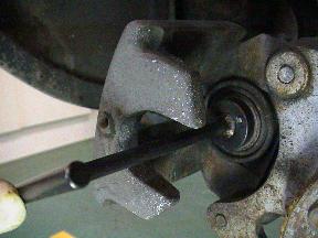
 With the piston extended check the rubber boot around the piston for signs of wear/splits/perishing. Also check the boots on the upper sliding pin (shown in the photograph). To do this move the caliper along the sliding
pins and check the rubber boots are still intact.
With the piston extended check the rubber boot around the piston for signs of wear/splits/perishing. Also check the boots on the upper sliding pin (shown in the photograph). To do this move the caliper along the sliding
pins and check the rubber boots are still intact.
![]() Sometimes simply winding the piston fully home into the caliper and extending it with the brake pedal as above several times is enough it.
Sometimes simply winding the piston fully home into the caliper and extending it with the brake pedal as above several times is enough it.
![]() If the piston will not move at all or is extremely stiff then it is a good idea to take the car to a professional and get their opinion.
If the piston will not move at all or is extremely stiff then it is a good idea to take the car to a professional and get their opinion.
Tools required
Materials required
Use a blunt flat-bladed screwdriver to remove any raised corrosion on the piston face, caliper 'arms' that hold the outer pad and retaining pin.
Push the piston back into the caliper using a piston winding tool. Remember that as well as turning the pison you will also need to push the tool/piston
into the caliper.
Put a very thin smear of copper grease on the corners of the brake pad backplate only where it comes into contact with the caliper.
You can also put some copper grease on the piston and the 'arms' of the caliper that hold the outer pad.
Insert the inner brake pad into the caliper ensuring that the backplate is next to the piston and the friction material is facing outwards.
Thoroughly clean the hub/drive flange and the inside of the centre of the disc to ensure the two mate properly.
Refit the disc onto the hub/drive flange.
Insert the outer brake pad between the disc and the caliper.
Place the anti-rattle spring in place and insert the retaining ping through the caliper, anti-rattle spring, outer pad, inner pad, anti-rattle spring and
caliper in that order. Ensure that the retaining pin has gone through both parts of the anti-rattle spring. You may need to use the hammer and
suitable pin to push the retaining pin fully home.
- Rear brake caliper pison winding tool
- 4mm allen key bit
- Small hammer
- Small pin (e.g. old nail)
- Blunt flat-bladed screwdriver
- Brake cleaner or methylated spirits
- Rag/cloth/tissue
- Copper grease
 If the old brake pads are to be re-used thoroughly clean them with brake cleaner or methylated spirits.
![]() Be extremely careful when scraping the piston that you don't damage/scratch the surface. Only scrape enough
to remove any high-spots of corrosion that may prevent the brake pad from fitting flat against the piston.
Be extremely careful when scraping the piston that you don't damage/scratch the surface. Only scrape enough
to remove any high-spots of corrosion that may prevent the brake pad from fitting flat against the piston.
![]() Always check the brake fluid level before and during this process in case there is too much
fluid in the reservoir and it overflows.
Always check the brake fluid level before and during this process in case there is too much
fluid in the reservoir and it overflows.
![]() Putting a thin layer of copper grease onto the hub/drive flange before fitting the disc will help prevent it
corroding and getting stuck in the future.
Putting a thin layer of copper grease onto the hub/drive flange before fitting the disc will help prevent it
corroding and getting stuck in the future.
![]() S2 only - take care to align the disc so that the retaining screw hole lines up. Refit the retaining screw. If you had to drill out the retaining screw or it was already drilled out make sure the 'stud' of the retaining screw is lined up with the hole in the disc.
S2 only - take care to align the disc so that the retaining screw hole lines up. Refit the retaining screw. If you had to drill out the retaining screw or it was already drilled out make sure the 'stud' of the retaining screw is lined up with the hole in the disc.
![]() The head of the retaining pin should be lower than the caliper body. If it is not it is not fully home. If you are
using a hammer you should notice a distinct change in sound when the pin is fully home.
The head of the retaining pin should be lower than the caliper body. If it is not it is not fully home. If you are
using a hammer you should notice a distinct change in sound when the pin is fully home.
Tools required
Materials required
The S1 has 19mm hex head nuts and the S2 has 17mm hex head bolts (with the special tool).
Put a thin smear of copper grease or similar on the outer face of the brake disc where it comes into contact with the road wheel. This will
help prevent the two corroding together. Also put a thin smear of copper grease on the road wheel studs/wheel bolts.
Carefully lift the road wheel into position. On an S1 this will mean placing the road wheel over the studs on the hub/drive flange. On an S2 you need
to make sure that the bolt holes in the wheel line up with the bolt holes in the disc.
Hold the wheel in place by placing your foot or knee gently against the bottom of the tyre and put the nuts/bolts back. At this stage just finger-tight is
sufficient.
Once all four nuts/bolts are in place and finger-tight use a socket handle to just nip them up a little bit more. Don't overtighten them but make sure the wheel isn't loose.
- 19mm socket
- 17mm socket
- Socket handle and extension bars
- Road wheel bolt special tool (S2 only - supplied with car)
- Road wheel locking nut/bolt key (supplied with car)
- Copper grease
- Rag/cloth/tissue
![]() It is worth putting a little copper grease or similar on the road wheel studs/bolts as it will help with
subsequent removal.
It is worth putting a little copper grease or similar on the road wheel studs/bolts as it will help with
subsequent removal.
![]() S1 only - covering the outside of the socket you use to tighten the road wheel nuts with
electrical insulation tape or similar will help prevent damage to the wheels.
S1 only - covering the outside of the socket you use to tighten the road wheel nuts with
electrical insulation tape or similar will help prevent damage to the wheels.
![]() S2 only - the S2 has a special tool for the road wheel bolts. This should be included with
the tool kit car for the car.
S2 only - the S2 has a special tool for the road wheel bolts. This should be included with
the tool kit car for the car.
Tools required
Lowering the car is the reverse of raising it - locate the jack/protective pad at the correct point and
raise the car clear of the support(s). Remove the support(s) and carefully lower the car until it is resting on
the floor.
- Suitable jack and protective pad (e.g. a piece of wood)
- Four ramps
Tools required
Torque settings
With the tyres in contact with something firm (the ground, a ramp etc.) use a torque wrench to tighten up the road wheel nuts/bolts
in the same sequence as they were loosened. The S1 setting is 85 Nm and the S2 setting is
105 Nm.
- 19mm socket
- 17mm socket
- Socket handle and extension bars
- Torque wrench
- Road wheel bolt special tool (S2 only - supplied with car)
- Road wheel locking nut/bolt key (supplied with car)
- S1 road wheel nut 85 Nm
- S2 road wheel bolt 105 Nm
![]() Make sure when you use the road wheel locking nut/bolt key that is firmly and squarely applied
to the nut/bolt. These keys have a tendancy to 'round' if they are not properly used.
Make sure when you use the road wheel locking nut/bolt key that is firmly and squarely applied
to the nut/bolt. These keys have a tendancy to 'round' if they are not properly used.
![]() S1 only - to fit the covers to the locking wheel nuts place the cover in the end of the black
plastic tube that the locking wheel nut key is stored in and then use the plastic tube to hold the cover against the locking wheel nut.
Use a long thin flat-ended tool (a socket extension bar is suitable) to press the cover over the locking wheel nut.
S1 only - to fit the covers to the locking wheel nuts place the cover in the end of the black
plastic tube that the locking wheel nut key is stored in and then use the plastic tube to hold the cover against the locking wheel nut.
Use a long thin flat-ended tool (a socket extension bar is suitable) to press the cover over the locking wheel nut.
![]() S1 only - make sure that you only fit the locking wheel nut covers to the locking wheel nuts. If the cover does not fit easily double-check that you aren't attempting to fit a cover to a normal wheel nut.
S1 only - make sure that you only fit the locking wheel nut covers to the locking wheel nuts. If the cover does not fit easily double-check that you aren't attempting to fit a cover to a normal wheel nut.
Materials required
To ensure the brake pads are in the correct position simply press and release the brake pedal repeatedly until it becomes firm. This is best done by sitting in the driver's seat and using the normal foot to ensure that it 'feels' as it should.
Do not be alarmed if the pedal goes all the way to floor on the first pumps - the mechanical and hydraulic advantage offered by the pedal and master cylinder mean that a complete pump of the brake pedal only moves the brake caliper pistons a small amount. This is exaggerated when more than one piston has been moved.
If the pedal does not become firm or feel correct go back and check any work you have done on the brakes. Never assume that the problem will resolve itself.
![]() After working on any part of the braking system always check that the pedal is firm before moving or driving the car.
After working on any part of the braking system always check that the pedal is firm before moving or driving the car.
- An assistant!
![]() If you have an assistant get them to attempt to push the car while you press the brake pedal. If you do not have an assistant drive the car slowly just a short distance and check that you can stop the car.
If you have an assistant get them to attempt to push the car while you press the brake pedal. If you do not have an assistant drive the car slowly just a short distance and check that you can stop the car.